FLAWS AND DEFECTS
Many flaws and defects can be avoided by using good part and tool design techniques. As a part designer it is a very good Idea to be aware of your options in tooling and to consider those while designing your part. For example, have potential gate locations in mind. Try to guess where knitlines will occur and how different gate locations will affect them. How easy will it be to trim the gate? The more parts you study, the better you will get at predicting flow. Be sure to communicate your intentions to the tool designer and get his feedback to influence your future designs.
Avoiding thick sections can add up to huge savings over the lifetime of a tool. Thick sections increase the cycletime of each shot, narrow the processing window, require overpacking, and cause reject parts.
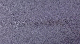
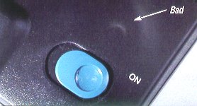
BLUSH DEFINITION: Dull discolored or whitish area on the surface of the part, usually at the gate. CAUSE: Shear stress between polymer molecules during injection. The gate may be too small or injection speed too fast. LOCATION: Usually at the gate. May also occur where there is a sudden change in part thickness. CURE: Adjust injection speed and if necessary adjust gate dimensions. An independent water circuit in the mold that allows pinpoint temperature control at the gate can also help. |
BLUSH |
BURN DEFINITION: Discoloration usually black, brown or dark yellow/brown depending upon severity. Feels rough and crunchy. Frequently accompanied by short shot in burn area. CAUSE: Usually indicates a need for more venting or heat buildup in tool. When air is trapped in the tool and cannot escape, the extreme pressure causes the air to ignite, burning the edge of the part. LOCATION: Most often seen in deep, blind ribs where a lot of air can be forced into a small space. CURE: Add more parting line vents near burn or vent pins in deep ribs. Vent pins are just ejector pins that fit a little loose. They may also have a flat ground down one side to let the air escape. |
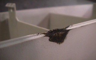 BURN |
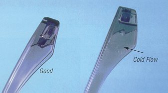
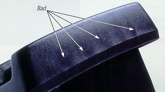
COLD FLOW DEFINITION: Wavy or streaked appearance on part surface. Looks like a fingerprint or small waves like you would see on the surface of water. CAUSE: Low melt temperature, low injection speed or low injection pressure. LOCATION: Hard to fill or last to fill areas. |
COLD FLOW |
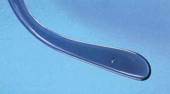
COLD SLUG DEFINITION: Cold piece of plastic that has been forced into the part along with the melt. CAUSE: 1.Plastic from last shot left in nozzle solidifies between shots. The tool designer usually is able to allow for a "cold slug well" in the runner to catch this piece. 2.Cold slug effects can also occur at the end of a long runner. LOCATION: If allowed to enter the part it can travel anywhere. CURE: Add a cold slug well at each intersection in the runner. Addition of a shortened ejector pin on the runner very close to the gate may divert the cold slug. For direct sprue gating try to make a feature in the part to catch the slug or use a heated nozzle. |
COLD SLUG |
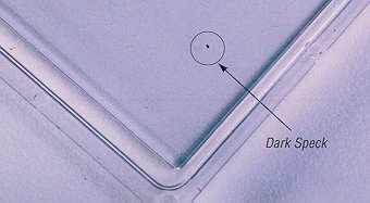
CONTAMINATION DEFINITION: Foreign particles embedded in the part. CAUSE: 1.Burned material in the press barrel. 2.Contaminated regrind. 3.Grease or particles that have not been cleaned from the mold. LOCATION: Anywhere. |
CONTAMINATION |
DELAMINATION DEFINITION: Separation of plastic surface layer giving a flaking or onion skin effect. CAUSE: 1.Contaminated resin. May be caused by incomplete machine purging, unclean material handling equipment or impure regrind. LOCATION: Anywhere. |
DELAMINATION or PEELING |
DISCOLORATION DEFINITION: Deviation from the original intended color of the material as compared to the manufacturers color chip. CAUSE: 1.Contaminated resin. 2.Overheated resin. 3.Incorrect regrind ratio. 4.Incorrect color mixing or blending. LOCATION: Entire part. |
DISCOLORATION |
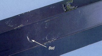
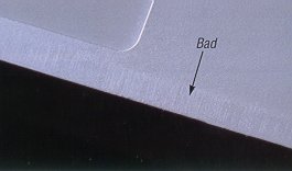
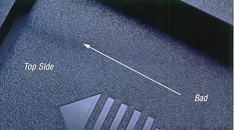
DRAG DEFINITION: Fine, straight lines scraped in the line of draw. CAUSE: Depends upon location. 1.Cavity side happens during mold opening and is usually from insufficient draft for the texture used or from overpacking. 2.Core side drag happens during ejection and is usually from inadequate draft, rough core, or overpacking. LOCATION: May be in opening direction or side action direction. Cavity, core, slide, or lifter. CURE: Solve overpacking problem. Cavity side drag, tone down the texture by stoning then bead blast. Core side drag, polish core, add draft. |
DRAG |
FLASH DEFINITION: Excess plastic squeezing out perpendicular to the part at parting line. CAUSE: 1.Plastic injection force exceeding the clamping pressure of the press. (Overpacking.) 2.May happen at first shots while mold is being dialed in. 3.Poorly constructed or worn out mold. LOCATION: Along any parting line. CURE: Run the mold in a bigger press. Relieve areas of the parting surfaces that are not immediately adjacent to the part. Leave 0.500 in. of shutoff land around the part. |
FLASH |
GLOSS DEFINITION: Smooth shiny areas on the part surface. CAUSE: 1.Underpacking 2.See section on plateout below. LOCATION: Hard to fill areas. |
GLOSS |
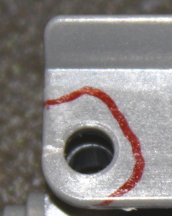
JETTING DEFINITION: Squiggly line in part pointing to gate. Looks like a worm in the part. CAUSE: 1.Incorrect gate placement or size. The gate is positioned in such a manner as to aim the plastic straight into an open area. The plastic launches out into the open like a piece of "silly string" and then stacks up in squiggles. LOCATION: Near gate. CURE: Aim the gate at an obstacle that interrupts the flow. Use different gate style or larger gate. |
JETTING |
KNITLINE DEFINITION: A line where the molten polymer flow fronts meet in the mold. Incomplete adhesion occurs along the knitline and causes a weak point in the plastic part. CAUSE: Cold fronts meeting in the tool where molten plastic fronts meet. LOCATION: Cold fronts meeting in the tool where plastic flows around obstacles or over raised areas in the metal. It is guaranteed that you will have a knitline as the plastic flows around any opening in the part. Recessed text or Icons can also cause small cosmetic knits. CURE: Frequently it is possible to place the gate in such a manner as to push the knit lines into obscure areas. If this is not possible use "flow directors" on the noncosmetic side of the part to push the knitline into a corner, crease, or shadow to hide it. Flow directors are usually just shallow raised areas in the plastic that are cut into the tool with a large ball end mill. Sometimes it is possible to add a "sump" that the cold material flows out into. This sump is then clipped off. |
KNITLINE |
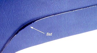
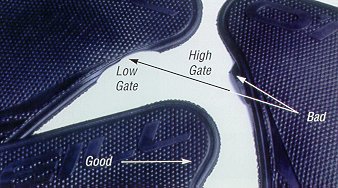
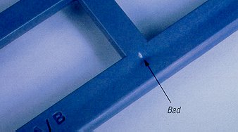
BAD GATE TRIM DEFINITION: Either too much or too little plastic where the gate has been trimmed off. CAUSE: 1.location of the gate on a concave or convex part surface can make it difficult to accurately trim the gate. 2.Another cause can be inadequately trained or uncoordinated people doing the trimming. LOCATION: Gate. CURE: Place the gate on a straight edge if possible. A good trim job takes good eye/hand coordination. Use of a gate trimming fixture can work well for high volume gate trimming. Use self degating techniques where possible such as tunnel gates or banana gates. Of course gating to a noncosmetic area is always preferred, but not always feasible. |
BAD GATE TRIM |
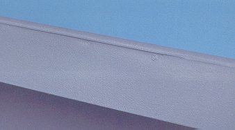
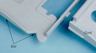
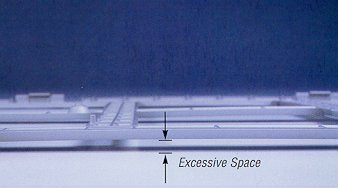
MISMATCH DEFINITION: The cavity side of the tool does not fall in perfect registry with the core side resulting in a step at parting line. It may look like flash if it is slight. If it is smooth as your finger runs across one way and feels sharp the other way it is mismatch. If you can feel it both ways it is flash. CAUSE: 1.Uneven pressure in the mold cavity can push the cavity one direction and the core the other. This usually happens in very asymmetrical parts or parts with a parting surface that slopes only one way. 2.Moldmaker did not properly position the cavity relative to the core. 3.In older tools mismatch may occur as locking faces wear. LOCATION: At parting lines. CURE: Straight locks at parting line. The best are those made by Progressive Components. |
MISMATCH |
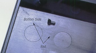
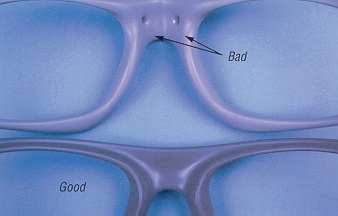
PIN PUSH DEFINITION: Circular or semicircular white stress rings on the side of the part opposite an ejector pin. May even be raised circular bumps. In serious cases pins may push right through the part! CAUSE: 1.Overpacking. 2.Sticking on the core. 3.Inadequate ejection. LOCATION: On the cosmetic side of the part opposite an ejector pin. CURE: Solve overpacking problem. Polish core or increase draft on core. Add more ejector pins. More small pins are better than a few big ones. |
PIN PUSH |
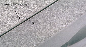
PLATEOUT DEFINITION: A change of mold texture over time that is not due to wear. CAUSE: 1.Buildup of chemical residue from outgassing. 2.Buildup of mold release. LOCATION: Anywhere CURE: Have the mold cleaned. |
PLATEOUT |
PULLING DEFINITION: Deformed, twisted and smeared plastic in the part usually on, or adjacent to steep vertical faces. CAUSE: 1.Cavity side: A portion of the part sticking to the cavity on tool opening. Listen to the mold as it opens to see if you can hear it pop free. 2. Core side: Uneven part ejection is not pushing the part out straight. The part gets skewed as it ejects, the resulting damage is called pulling. LOCATION: Anywhere in part. CURE: Cavity side pulling, add undercuts or texture on core side so part pulls cleanly from the cavity. Core side pulling, add ejection. More small pins are better than a few big ones. |
PULLING
|
SHORT SHOT DEFINITION: Missing plastic or features that are not fully formed. Missing corners or features have a smooth, rounded appearance. CAUSE: Underpacking, low injection pressure, trapped gas. LOCATION: Areas of the part farthest from the gate, thin areas or delicate features. Generally the last part of the mold to fill. CURE: Make sure the tool is adequately vented and push more plastic in. |
SHORT SHOT |
SINKS DEFINITION: Depressions or dimples in the part that are usually adjacent to thick areas. In clear parts, bubbles can be seen in thick areas. These bubbles can be the precursors of shrink. CAUSE: As the plastic cools it shrinks. If there is an area that is proportionally thicker than the rest of the part, then the plastic will shrink more in the thick spot causing it to collapse inward. LOCATION: 1. Wall perpendicular to ribs or bosses that don't conform to the 66% rule. 2. Inconsistent wall thickness. i.e. Thick areas adjacent to thin areas. CURE: Maintain constant wall thickness by coring out. If you must have thick areas lead gradually into them. Follow the 66% rule for wall thickness. Keep it down to 60% or less if you can. Frequently the solution to sink is to pack the part out tighter. Overpacking can then cause other problems. The best solution is to avoid it in the first place with good part design. Other problems that can be caused by sink include part warpage, twisting, stress, and part breakage. For more info visit the ribs and bosses section of this website. |
SINK
VOID or DEEP SINK
BUBBLE |
SPLAY DEFINITION: Silver or whitish streaks CAUSE: 1.Moisture in material. 2.Overheated material. LOCATION: Anywhere. Most predominant near gate. |
SPLAY |
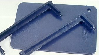
WARP DEFINITION: The failure to maintain flatness of a plastic part that was intended to be flat. Distortion from the intended shape of the plastic part. CAUSE: 1.The underlying cause of most part warpage is the shape of the part itself. The pattern, shape, and thickness of ribs on the part as they undergo shrinkage have the greatest effect upon warpage. These effects can be controlled to some degree by differential cooling of the mold (a different temp on the cavity than on the core). 2. Overpacking can induce warp. LOCATION: Present to some degree in most Injection molded parts but most easily detected on large flat parts. CURE: Alas there is no cure for this one, only control. Differential mold cooling can get you parts that are flatter. A cooling fixture that the part is placed into immediately after ejection can also straighten the part. However these effects are usually temporary and upon being subjected to elevated temps or time parts will return to their natural shape. Your best bet is to follow the 66% rule and minimize rib height. Flat parts are more susceptible to warpage than curved parts. Note: On long thin flat parts the gate is best placed between 60-70% down the part length to minimize warp. -------------------------------------------------------------------- |
WARP |
PHOTOS COPIED FROM SUN MICROSYSTEMS COSMETIC AND STRUCTURAL DEFECTS MANUAL
PHOTOS USED WITH PERMISSION OF SUN MICROSYSTEMS
![]()